- 您现在的位置:买卖IC网 > Sheet目录3813 > PIC18F452-I/ML (Microchip Technology)IC MCU FLASH 16KX16 A/D 44QFN
Micrel, Inc.
KSZ8864RMN
April 2012
13
M9999-043012-1.5
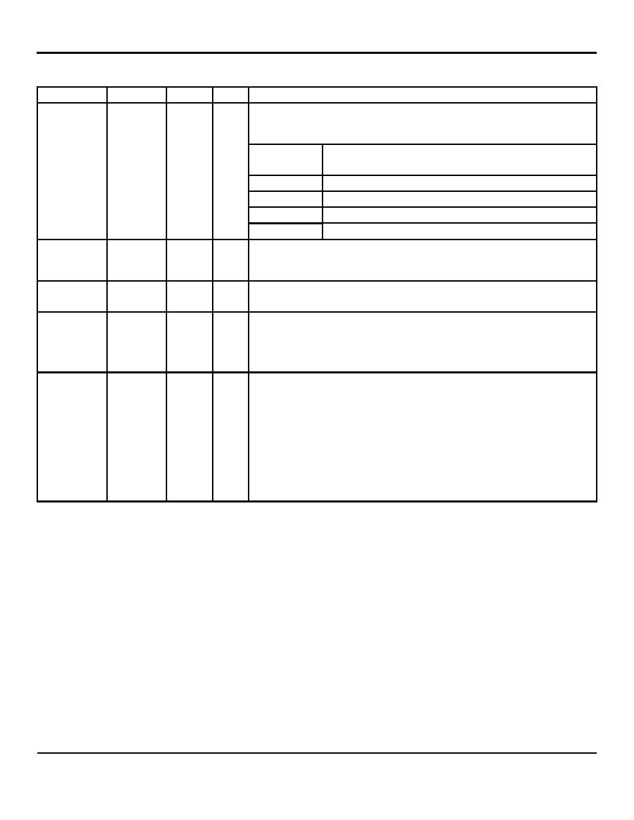
Pin Description (Continued)
Pin Number
Pin Name
Type
(1)
Port
Pin Function
(2)
MAC4 Switch SW4-MII enabled with PHY mode or MAC mode, have to configure
SCONF1 Pin 47 with SCONF0 Pin 48 together.
See pins configuration table below:
Pin# (47,48)
Port 4 Switch MAC4
SW4- MII
00 (Default)
SW4-MII PHY mode
01
Disabled
10
Disabled
47
SCONF1
IPD
11
SW4-MII MAC mode
48
SCONF0
IPD
Port 4 Switch SW4-MII enabled with PHY mode or MAC mode, have to configure
SCONF0 pin 48 with SCONF1 Pin 47 together.
See Pin 47 description.
49
P2LED1
IPU/O
2
LED indicator for Port 2.
This pin has to be pulled down by 1K resistor in the design for KSZ8864RMN.
50
P2LED0
IPU/O
2
LED indicator for Port 2.
Strap option: Switch MAC3 used only.
PU (default) = Select MII interface for the Switch MAC3 SW3-MII.
PD = Select RMII interface for the Switch MAC3 SW3-RMII.
51
P1LED1
IPU/O
1
LED indicator for Port 1.
Strap option: Switch RMII used only.
PU (default) = Select the device as clock mode, when use RMII interface, all
clock source come from pin x1/x2 crystal 25MHz.
PD = Select the device as normal mode when use RMII interface. All clock
source comes from SW4-RMII SM4TXC pin with an external input 50MHz clock.
In the normal mode, the 25MHz crystal clock from pin X1/X2 doesn’t take affect
and should disable SW4-RMII SW4RXC 50MHz clock output by the register 87.
The normal mode is used when SW4-RMII receive an external 50MHz RMII
reference clock from pin SM4TXC.
发布紧急采购,3分钟左右您将得到回复。
相关PDF资料
PIC18F452-I/PT
IC MCU FLASH 16KX16 EE 44TQFP
PIC18F6622-I/PT
IC PIC MCU FLASH 32KX16 64TQFP
201828-1
CONN JACKSCREW SHORT-SHORT FMALE
608489070001049
CONN CONTACT FOR 8483/8484 PLUGS
PIC18LF258-I/SO
IC MCU CAN FLASH 16K LP 28-SOIC
DSPIC33FJ256GP710-I/PT
IC DSPIC MCU/DSP 256K 100TQFP
9-1469373-9
CONN GUIDE MOD FEMALE R/A
PIC32MX460F256L-80V/PT
IC MCU 32BIT 256KB FLASH 100TQFP
相关代理商/技术参数
PIC18F452-I/P
功能描述:8位微控制器 -MCU 32KB 1536 RAM 34I/O RoHS:否 制造商:Silicon Labs 核心:8051 处理器系列:C8051F39x 数据总线宽度:8 bit 最大时钟频率:50 MHz 程序存储器大小:16 KB 数据 RAM 大小:1 KB 片上 ADC:Yes 工作电源电压:1.8 V to 3.6 V 工作温度范围:- 40 C to + 105 C 封装 / 箱体:QFN-20 安装风格:SMD/SMT
PIC18F452-I/P
制造商:Microchip Technology Inc 功能描述:IC 8BIT FLASH MCU 18F452 DIP40
PIC18F452-I/PG
功能描述:8位微控制器 -MCU 32KB 1536 RAM 34I/O RoHS:否 制造商:Silicon Labs 核心:8051 处理器系列:C8051F39x 数据总线宽度:8 bit 最大时钟频率:50 MHz 程序存储器大小:16 KB 数据 RAM 大小:1 KB 片上 ADC:Yes 工作电源电压:1.8 V to 3.6 V 工作温度范围:- 40 C to + 105 C 封装 / 箱体:QFN-20 安装风格:SMD/SMT
PIC18F452-I/PT
功能描述:8位微控制器 -MCU 32KB 1536 RAM 34I/O RoHS:否 制造商:Silicon Labs 核心:8051 处理器系列:C8051F39x 数据总线宽度:8 bit 最大时钟频率:50 MHz 程序存储器大小:16 KB 数据 RAM 大小:1 KB 片上 ADC:Yes 工作电源电压:1.8 V to 3.6 V 工作温度范围:- 40 C to + 105 C 封装 / 箱体:QFN-20 安装风格:SMD/SMT
PIC18F452-I/PT
制造商:Microchip Technology Inc 功能描述:8BIT FLASH MCU SMD 18F452 TQFP44
PIC18F452-I/PTC28
制造商:Microchip Technology Inc 功能描述:
PIC18F452-I/PTG
功能描述:8位微控制器 -MCU 32KB 1536 RAM 34I/O RoHS:否 制造商:Silicon Labs 核心:8051 处理器系列:C8051F39x 数据总线宽度:8 bit 最大时钟频率:50 MHz 程序存储器大小:16 KB 数据 RAM 大小:1 KB 片上 ADC:Yes 工作电源电压:1.8 V to 3.6 V 工作温度范围:- 40 C to + 105 C 封装 / 箱体:QFN-20 安装风格:SMD/SMT
PIC18F452IL
制造商:Microchip Technology Inc 功能描述: